



Topologies
The Right Topology for Your Application
The requirements of your application determine the degrees of freedom your power electronics must offer—from voltage regulation to bidirectional energy flow. Whether it’s a battery test system, smart grid, electrolysis, or megawatt charging—the requirements for modern power electronics vary considerably. What matters is not just the power, but above all:
- Does energy need to flow bidirectionally?
- Is galvanic isolation required?
- Is a step-down converter sufficient?
- Does the voltage need to be flexibly increased and decreased?
- Are series or parallel connections required?
The knestronX Rack allows you to select and combine different topologies—tailored to the degrees of freedom of your application.
Decision-Making Process
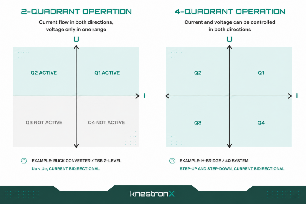
Step 1 – 2Q or 4Q?
|
2-Quadrants
|
4-Quadrants
|
|---|---|
|
Current is bidirectional Voltage is only in one direction Vout< Vin
|
Current and voltage are fully controllable Can be increased or decreased Vout≤ ≥ Vin
|
Suitable for
-
- Battery Test Systems
- Energy Conversion
- Charging/Discharging Processes
- Smart Grids
- Battery Simulation
- Simulation of electric drive components,
- Fuel cell test systems
- Short-circuit test systems
- Megawatt Charging (MCS)
- Electrolysis systems
Step 2 - Is galvanic isolation required?
Electrical isolation is required when:
- there are different ground potentials
- safety requirements increase
- serial output circuitry is required
- sensitive test environments are in use
With electrical isolation:
Bidirectional resonant converter is required
With Bidirectional resonant converter, is the input voltage greater than or less than 800 VDC?
Greater than => balancer required; less than => no balancer
Without galvanic isolation:
direct 2L Buck Converter/2L H-Bridge Converter solution possible
Step 3 – What voltage range is required?
Input Voltage Range
Up to 800 VDC:
- Standard version
- No balancer required
- Compact design
- High currents possible
- Reduced complexity
800–1500 VDC:
- Balancer required
- Higher power density
- Lower currents
- Additional degrees of freedom
Output Voltage Range
Up to 800 VDC:
- parallel connection of outputs possible
- higher currents possible
800–1500 VDC:
- serial connection of outputs and Bidirectional resonant converter required
- full power range
We'll guide you through the decision-making process
An overview of topologies
2L - Buck Converter
- Typical Applications: High-current and rugged DC/DC applications
- Voltage characteristics: Vout< Vin(voltage regulator)
- Isolation: no
- Quadrants: 2Q
- Vmax = 800 V / Imax = 700A
HTSB
- Typical Application: Higher Voltages and Power Densities
- Voltage characteristics: Vout< Vin(voltage regulator)
- Isolation : no
- Quadrants: 4Q
- Vmax = 1500V / Imax = 350A
2L H-Bridge Converter
- Typical Applications: Simulation and Dynamic Test Systems
- Voltage behavior: Ua ≤ ≥ Ue (rising and falling edges)
- Isolation: optional
- Quadrants: 4Q
- Vmax = 800 V / Imax = 350A
Bidirectional Resonant + 2L - Buck Converter
- Typical Applications: Battery Test Systems & Smart Grids
- Voltage characteristics: parallel: Vout< Vin | series: Vout< 2 × Vin
- Isolation: yes
- Quadrants: 4Q
- parallel: Vmax = 800 V / Imax = 700A
- series: Vmax = 1500 V / Imax = 350A
Balancer + Bidirectional Resonant + 2L - Buck Converter
- Typical Applications: MCS, Electrolysis, and High-Voltage Systems
- Voltage characteristics: parallel Vout < ½ x Vin | serial Vout < Vin
- Isolation: yes
- Quadrants: 4Q
- parallel: Vmax = 750 V / Imax = 700A
- serial: Vmax = 1500 V / Imax = 350A
Balancer + Bidirectional Resonant + HTSB
- Typical Applications: Electrolysis and Megawatt Charging
- Voltage characteristics: Vout< 2 × Vin
- Isolation: yes
- Quadrants: 4Q
- Vmax = 1500V / Imax = 350A
Balancer + Bidirectional Resonant + 2L H-Bridge Converter
- Typical Applications: Battery Simulation and Fuel Cell Test Systems
- Voltage characteristics: Vout ≤ ≥ Vin
- Isolation: yes
- Quadrants: 4Q
- Vmax = 750 V / Imax = 350A
Rethinking Power Electronics?
You know your application—we'll define the right topology. We look forward to hearing from you!
Address
Osterwalder Str. 12 87496 Hopferbach Germany
Phone
+49 8372- 7080
powered by
